
Building a Shutter Tester

After repairing a shutter, the logical continuation is its setting. I initially made a first adjustment "by ear." I also tried to get information about the usual method, to discover with amazement that the "by ear" method was the rule (even at the factory, as my tests will confirm later) I also discovered there is a book about repairing the Fed, Zorki and Zenit (written by Isaac Maizenberg in Russian, the English version seems impossible to find anymore), which also recommends this method of adjustment.At the photo school, we made shutter tests using a "Spectron", electronic device which at the time eqiped some photo stores. It seems that since the 1980s, this kind of toy is now impossible to find, or unaffordable.Several Internet users have built their own assembly : see this site which also links to other sites. The trick is to make a tester connected to the sound card, and use a sound editing software to calculate the exposure time.Here is my own making. My difference is the idea of using, instead of simple phototransistors, optical fiber and sensors, which can allow the use of several models of sensors (for vertical, horizontal shutter, for 6x6 ...) with a single electronic circuit.
The electronic board

The parts:2 receivers for fiber optics1 set of 47ohm resistors1 set of 390ohm resistors2 100 nf capacitors2 meters of optical fiber2 5mm red LEDs1 case for 3 R6 batteries, equipped with a switch1 stereo cable with 2x stereo 3.5 male jacks1 "test" board for electronic assemblies.The adjustable resistor on the photo was not used. The assembly needs one 47ohm and two 390ohm resistors, but my supplier sells by sets of 5. The sensors have disappeared from my supplier's catalog, so I don't give their reference, but these kinds are relatively easy to find, the resistors and capacitors values have to be adapted according to the manufacturer's datasheet.
 Here is the diagram as it appears in the sensor manufacturer's datasheet: after a few tests, it's as-is that it should be used (in double, obviously, to get a "stereo" tester) the aim of the capacitor is to improve the signal, I saw by another supplier that it should be as close as possible to the sensor. Without resistor, the output signal is too weak.
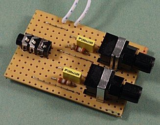
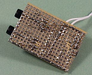 The final assembly:After several trials (with or without resistors or capacitors), I remade a "clean" workI had originally planned to cut the audio cable and solder the wires on the card, finally I used a chassis socket (taken from an out-of-order CD reader).Problem: the sensors' maker indicates that they operate at 5V, and I thought I could use a 4.5V supply using a box for 3 R6 batteries; error: with 4.5V there is no output signal, I had to use a 5v supply. The 4.5V power supply will be used for the LEDs.
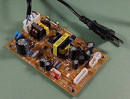 Power supply:To adapt my Photosniper to Canon EOS, I used switches recovered from a DVD player, now comes the power supply from this DVD player! Output 3.3V, 5V, ±12v, this supply may often be useful, I will seriously think of finding a case for it!Another solution: supplying my assembly via USB, provided to have a PC equipped with USB 2.0. My laptop uses USB 1, and I did not take the risk of damage if my circuit is too heavy on power.
The probe
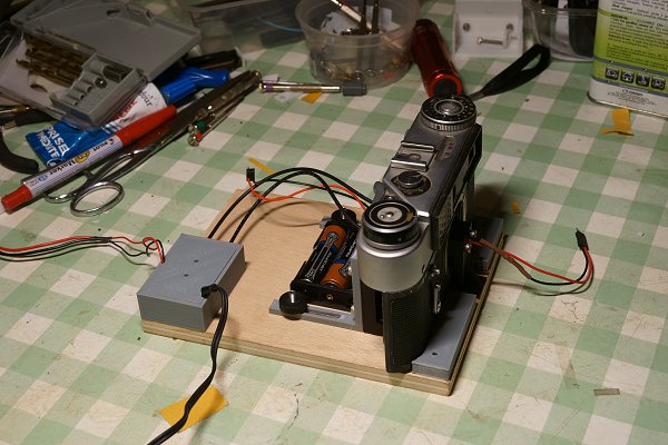
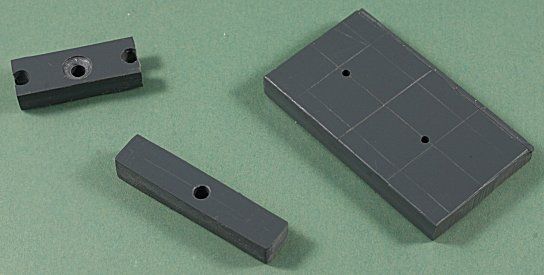 I have in my stocks thick (~ 1cm) PVC plates, perfect to make the probes. I prepared a part adapted to the size of the window of my Soviet cameras (width equal to the width of film guides (35mm) length is the one of the plate in which I made the cut) The other two parts are for the holder for diodes that provide lighting from inside the body. The drilling position results of the diameter of diodes (as these LEDs are 5mm diameter, it's at 2.5mm of the edges of the 24x36 window) diameter of the holes:2.2mm corresponding to the diameter of optical fibers.
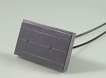
 Remains to fix two 30cm strands of fiber optic: push leaving a few millimeters, stick with cyanoacrylate glue, then cut flush with a well sharpened tool.
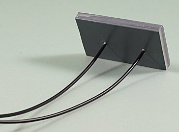
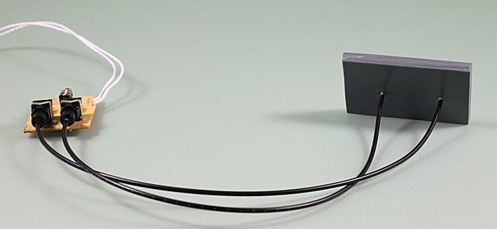 Ready!
LED holder
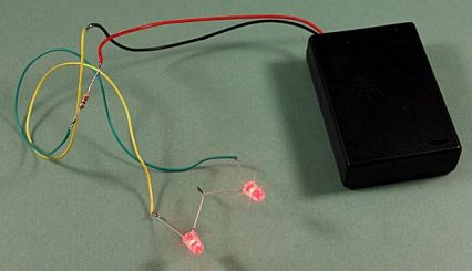 A sensor like the one I just realized does not work alone, it needs a relatively strong light source. I made some tests using a small 50w halogen, that works well but it's not always convenient to succeed in keeping the camera in front of the lamp. To test my Fed, I had the idea to use LEDs on a stand placed inside the body. As my sensors are sensitive to red (660 nm) I bought red diodes. They are serial wired with a 47 ohm resistor on my box for 3 R6 batteries.
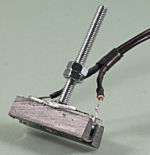
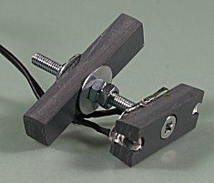 The diodes are mounted on the support drilled at the same gap as for the probe. The whole mounted using a long screw and washers on one leg.

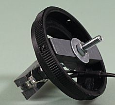 The hole is wider than the axis to allow adjustment, the whole is finally put into a "A" M39 ring (see "T2 Rings")which goes screwed in place of the lens. One of the screws normally used to set the ring on a lens is used to hold the "LED-holder".
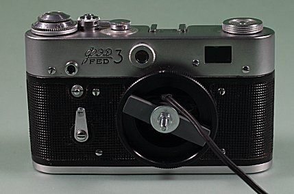
 The LEDs in place into my FED 3.
End of the assembling
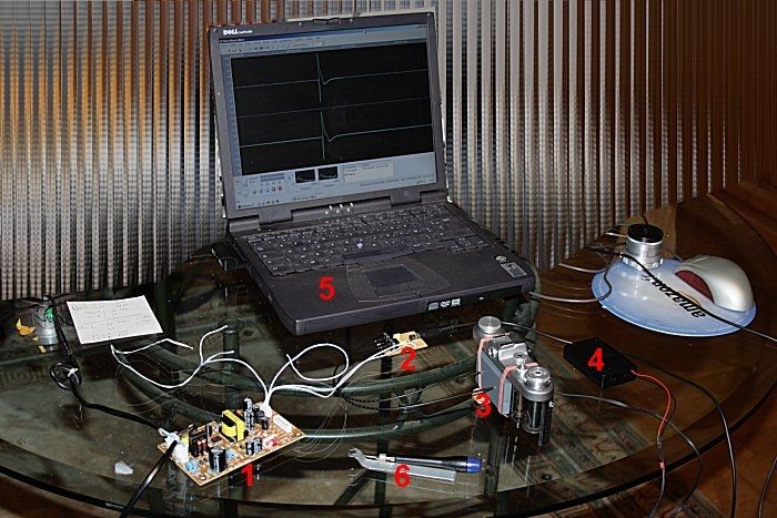
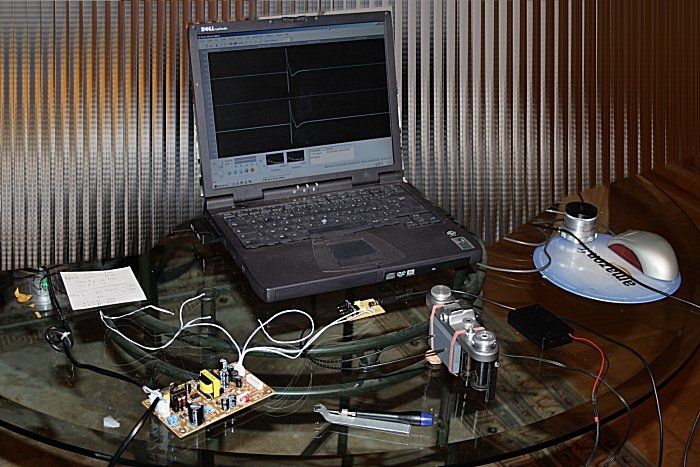
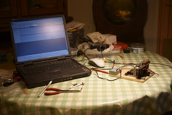
The whole in running order:1: my 5V power supply2: The electronics card, linked to the supply, and with the stereo cable to the "line" input of the sound card.3 The probe adjusted to the FED ZARIA with elastic bracelets.4: The power for the LED.5: My laptop computer, the display shows the sound editing software.6: Even the tools to set the shutter!
Using
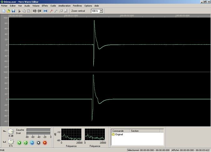
For the explanations, I chosed Nero wave editor, software provided with Nero. We'll see that it is not the ideal, but it's screen captures are easy to read.Here is the curve that appears after recording (cock the camera, tester and diodes switched on, start recording, release the shutter, stop recording):
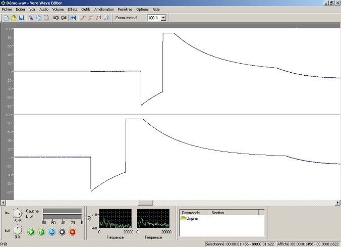
Select the "interesting" part of the curve:

Zoom in on the selection (icon: ![]() )
)
Eventually select and zoom in again for more precision:
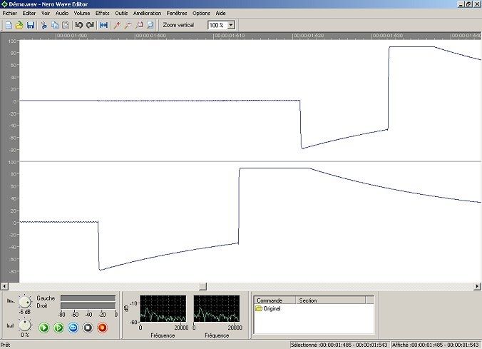
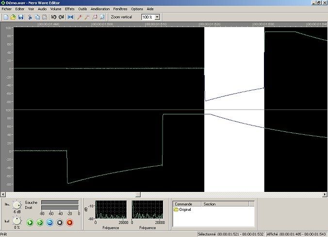
I have selected here the part of the curve corresponding to the first sensor, so the exposure time to the right:
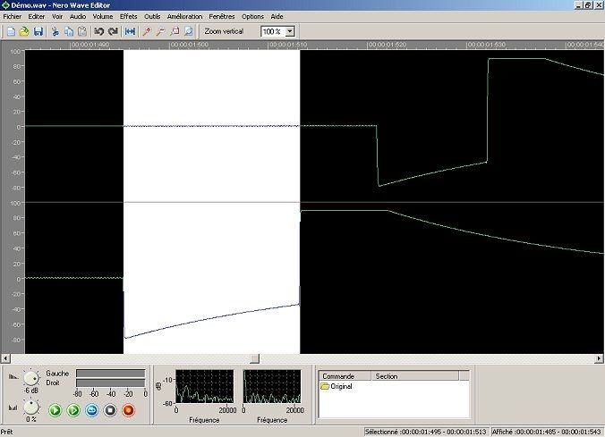
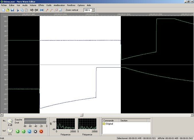
And here the part corresponding to the 2nd sensor, to the left. The software displays the time-coordinates of the selection:right sensor: 1,513s - 1,495s = 0.018s, or about 1/56sleft sensor: 1,532s - 1,521s = 0.011s, or about 1/91sSo that is what my FED3 gives for 1/60s!
The two other points to consider are the time between the illuminations of the sensor 1 and the sensor 2:
And the time elapsed between their extinctions:
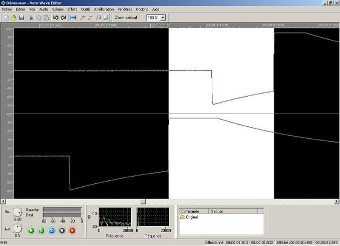
What makes it possible to compare the relative speeds of the two curtains:Curtain 1: 1.521s - 1.495s = 26msCurtain 2: 1.532s - 1.513s = 19ms
These results will allow:1. check of the various exposure times of my cameras,2. to eventually carry out an adjustment, playing on the tension of the curtains to balance their speeds.Warning: Nero wave editor rounds values to 0.001, this accuracy is not enough, there is no intermediate values between 1/1000 (0.001) and 1/500 (0.002)!For the future, I will use Audacity, freeware software, which displays at 1 / 100 000s (and it displays the duration of the selected area, just reverse (and round) to get a result in 1 / x form).
Résults
Below is a table of the results of measurements on some of my cameras. For every theoretical speed, I show the speeds at first and second sensor:
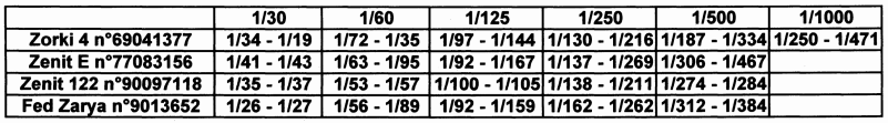 First, as a reference: the Zorki 4 and Zenit E with which I have done many photos (with no serious exposure errors), and which shutter settings have never been touched since their purchase.Then, the Zenit 122, latest camera, to see if the shutter and it's setting method have changed over time.Finally, the Zarya, after I have settled it.The results of Zorki 4 highlight a feature that I could find on several bodies: at slow speeds, the 2nd curtain is slower than the first, this is reversed when you go towards fast speeds. It is also understandable that the designers did not attempt to generalize the 1/1000s speed on their cameras!The Zenit E is the only camera that has been tested at the school photo in 1980 (average exposure time measured with a single cell, in the middle), the results are consistent with what I remember.The Zenit 122 seems pretty well settled, with a smaller gap between the two sides measurements (the results of Zenit 130, mechanically identical, are close).Finally the results of my Zarya, after setting: I tried to get close speeds for the two curtains. In light of these results, I might try to raise a little the tension of curtain 1, but the setting is 1 / 2 turn of the screw around on this model and the accuracy may be insufficient to get better.I have not shown the results of my Fed 3: The curtains seemed much more tightened than those of other cameras, the measures have given the 1/30s close to 1/70s! after an initial adjustment to return to more suitable values (but which needs to be further refined) this body that I found very noisy gained discretion.What I learned from my first steps in the setting of Fed - Zorki - Zenit shutters:The second curtain must be adjusted first, and then try to align the speed of the No. 1 (on the Zarya, I had to decrease the tension of the No. 1, because No.2 's speed couldn't increase)Too tightened curtains make a noisy camera.Do not deal with the 1/500s, it hardly reaches 1/350s on all cameras (and ignore the 1/1000s!)It is good for morale to take next a few photos, to realize that even if the measures are not wonderful, the important thing is that it takes good pictures anyways!
Thank you to Chris Elsass for his precious advice in electronics.
*** 2019 ***
Here is a new assembly built in december, thanks to my recently acquired 3D printer:
 For testing a FED 1, the camera body must be open. A new holder for the LED (narrower), a plate in front of the bottom of the shutter with two wedges to hold the camera in place.On the back another part wedged by two brackets holds the optical fibers in regard with the LED's. The whole fixed on a board.
I also made a box for the electronic board.
 Another version for FED 2, 3, 4, and 5 (Here with a FED 5)
Two different wedges on the front...
 ... and on the back another plate adapted to the shutter molding.
And still the same computer.